
3. Instrumentation and physical principles of carotid (Duplex) ultrasound

What you need to know before you start to practice carotid ultrasound.
3.1 Which ultrasound scanner and transducer should you use?
Carotid ultrasound is performed with a linear array probe. Such probes have a large aperture and provide high spatial resolution in the near field. Handheld ultrasound systems have been found to be comparable to mid and high range ultrasound systems (for point of care purposes). In general, it is advised to use scanners with high spatial and temporal resolution since soft plaques can easily be missed if image quality is poor.
It is recommended to optimize your settings and to define presets specifically for carotid Duplex ultrasound. Aside from a good (high resolution B image) you will need color Doppler functionality and pulsed wave (spectral Doppler) to assess flow and to quantify the degree of stenosis. Many systems also offer automatic spectral Doppler tracking (automatic velocity measurements) or automated intima media thickness calculations. In addition, you will find vendor specific color and B-Mode flow options such as: power Doppler or B mode flow. Recently there has been large interest in contrast enhanced carotid (CEUS) ultrasound. This modality provides improved flow visualization, helps to differentiate true structures from artifacts, plaque delineation (ulcerations?) and to detect neovascularization of plaque. Specific settings are required for contrast-enhanced ultrasound (CEUS).
3.2 Which settings are important when scanning the carotid arteries (carotid ultrasound)?
- Adjust the brightness and contrast of the monitor first! The setting you chose depends on the lighting of the room. The brighter the room the brighter you will also need to adjust your monitor.
- Use a high imaging frequency. The higher the imaging frequency the better is the spatial resolution (however you will loose penetration).
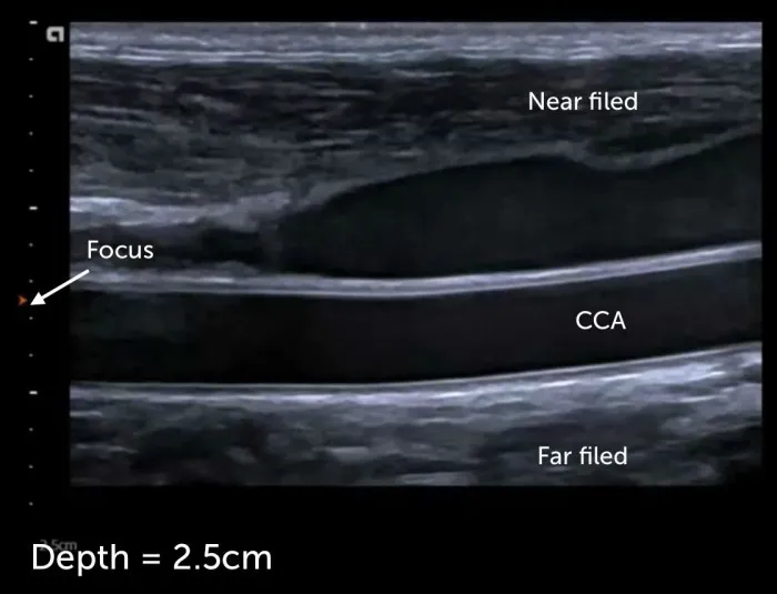
- Adjust the depth to make sure that the artery fills the screen and that structures posterior to the carotid artery can still be seen (depth setting is usually 2-3cm)
- Adjust the focus point at the level of the arteries
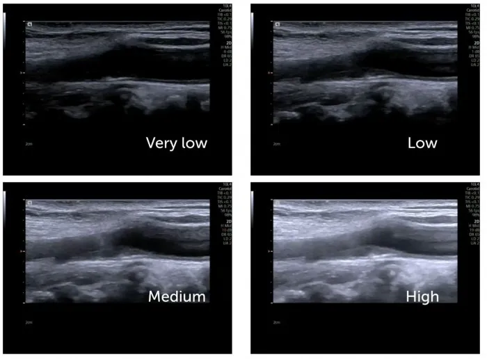
- Adjust the gain (avoid over- or under gaining)
- Adjust the time gain compensation
- Image contrast: a higher contrast helps to delineate “boarders” but the higher the contrast the less tissue information you get (you have less shades of gray in the image)
- Tissue harmonic imaging: is a technique where the harmonic properties (resonance) of tissue are used to create the image. Its main advantage is that you have fewer artifacts. This modality is the preferred mode of imaging. Don’t turn it off!
- Compound imaging: combines images from several steering angles to one image. Using multiple images to look at a specific region reduces artifacts and noise form the image.
Note: many scanners have an image optimization button (auto optimization) that adjusts the gain and the contrast. While this button is often helpful, don’t rely to heavily on this function.
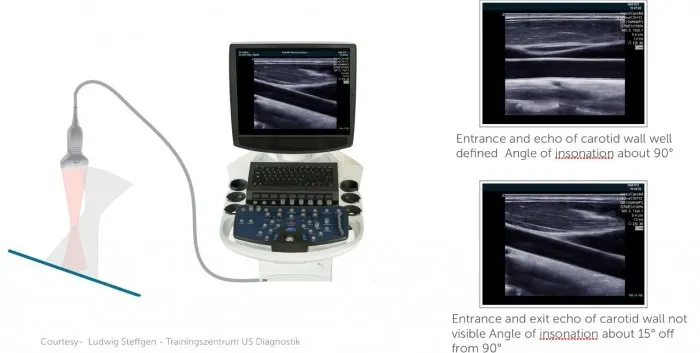
3.3 What is the angle of insonation in carotid ultrasound?
The angle of insonation is defined as the angle with which the ultrasound beam hits the surface of a certain structure (i.e. the carotid artery wall). The more perpendicular the angle (90°) of insonation is the more ultrasound rays are reflected back to the ultrasound transducer and the better the image quality will be.
Angle of insonation
| Angle of insonation |
|---|
| The angle of the ultrasound beam relative to the tissue (vessel wall) |
| The strongest echo are produced when the angles of incidence approaches the angle of reflection |
| The best B Mode image is achieved if the structure is hit perpendicular (90°) |
| The angle of insonation plays an important role when using color Doppler |
3.4 What is pulsed wave (PW) spectral Doppler in carotid (Duplex) ultrasound?
Pulsed wave Doppler
| Pulsed wave Doppler |
|---|
| In carotid ultrasound we use mainly pulsed wave Doppler (PW-Doppler) |
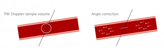
| With PW Doppler we are able to measure blood flow velocity within a sample volume |
| The Doppler velocities we measure are very dependant on the angel between the blood flow direction and the transducer |
| The more the angle moves towards 90° the higher the measurement error will be. |
| Therefore we use angle correction. We tell the scanner in which angle blood is actually flowing |
| The principle of Doppler is used in color- and spectral Doppler |
| Blood flow moving towards the transducer is depicted in red (color Doppler) |
| Blood flow moving towards the transducer is depicted in blue (color Doppler) |
| Blood flow moving toward the transducer is depicted above the baseline (spectral Doppler) |
| Blood flow moving away from the transducer is depicted below the baseline (spectral Doppler) |
| The shade of color (yellow-red, light blue - dark blue) allows us to semiquantitatively assess the velocity of blood flow |
3.5 What is Color Doppler (Duplex)?
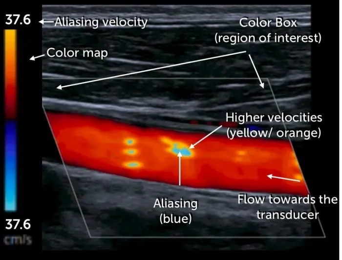
Color Doppler ultrasound uses the same principles as pulsed wave Doppler. Within a region of interest (ROI – Color Doppler box) the system looks at many different “sample volumes or pixel areas” and calculates the velocity and direction of flow (for each individual area). This information is then encoded in color according to a color map scheme (which can be chosen by the operator) and displayed for each imaging frame (dynamic color flow imaging). Usually flow towards the transducer is depicted in red and colors away from the transducer in blue (unless the color encoding is inverted).
The color map also assigns a different shade of color to the absolute velocity of flow. Usually the lighter the color (yellow or light blue) the higher the velocity. Note that a color shift occurs if velocities surpass the aliasing velocity (also called Nyquist limit). Color Doppler allows us to directly visualize flow (visualize vessels) and helps us to see areas where the flow velocity is elevated (aliasing).
3.6 What is aliasing in ultrasound and how do we use it during carotid Duplex sonography?
Aliasing
| Aliasing |
|---|
| Is a Doppler phenomenon where the intermittent sampling rate (PRF) is too low to record a certain velocity |
| This results in an inability to measure the true velocity and flow direction |
| It occurs in both color and PW Doppler (because both of theses techniques use „intermittent„ sampling) |
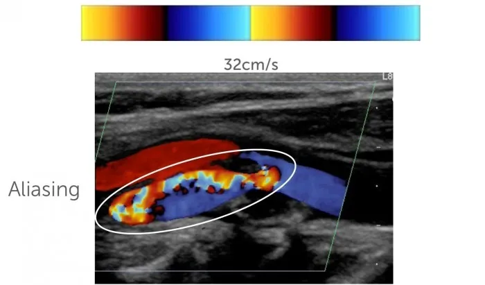
| In carotid Doppler this results in a sudden shift from red to blue or blue to red, we often see a mosaic of different colors |
| Aliasing is helpful in US because it allows us to quickly detect regions where blood flow velocity is high |
| High blood flow velocity can be present in stenosis or tortuous vessels |
| The velocity at which aliasing occurs can be set on the scanner (PRF, aliasing velocity, Nyquist limit) |
| The value depicted on the color bar tells us at which velocity aliasing occurs. |
3.7 Carotid ultrasound – artifacts
Artifacts are alterations in the image, which are not true structures but produced by physical phenomena of ultrasound and its interaction with tissue. Artifacts can occur in both good and poor image quality and typically occur with implants (i.e. metallic stents) It is important to know which potential artifacts can occur to avoid misinterpretation and misdiagnosis. Here are the most common forms of artifacts:
| Artefacts | Explanation | Examples |
|---|---|---|
| Acoustic enhancement | Structure posterior to tissues that transmits US well is enhanced | Posterior enhancement behind cysts, urinary or gallbladder |
| Acoustic shadowing | The US waves are completely absorbed or reflected (solid structures). Structures behind such tissue is not visible | The vessel posterior so a calcified plaque can not be visualised. Prosthetic material, bone (rib shadow) |
| Beam width artifact | When the ultrasound beam is wider than the diameter of the reflector being scanned. Adjacent structure are included into the beam and displayed as false structures | When scanning an anechoic structures (Cystic structures) they might appear solid |
| Blooming artifact | When the color Doppler signal extends beyond the true boundaries of the vessel, spreading into adjacent regions with no actual flow | Over gaining of color Doppler (A structure in a vessel might be overlapped by color and thus missed (Carotid US) |
| Mirror Image artifact | Mirror image artefacts occur in the presence of strong reflectors. The wave is reflected several times and structures are displayed several times | Pericardium, diaphragm, echogenic, reflection of liver lesion into the thorax |
| Reverberation | When the US beam reflects back and forth between two strong parallel reflectors. Appears similar to mirror artefacts | Comet tail artefact in lung ultrasound, |
| Near field clutter | Near field clutter occurs due to high amplitude oscillations of piezoelectric crystals. It involves the near field and may hinder identification of structures that are close to the transducer | Echocardiography, display of false apical structures (which are close to the transducer in an apical view). |